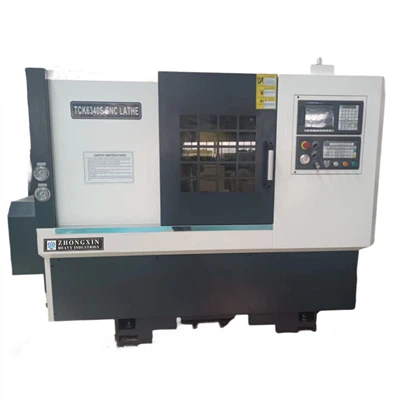
Calibrating a gap bed lathe is a crucial process that ensures the machine operates at its optimal performance, delivering precise and accurate results. As a trusted gap bed lathe supplier, we understand the importance of proper calibration in maintaining the quality and reliability of these machines. In this blog post, we will guide you through the step-by-step process of calibrating a gap bed lathe, highlighting key considerations and best practices along the way.
Understanding the Basics of a Gap Bed Lathe
Before diving into the calibration process, it's essential to have a basic understanding of what a gap bed lathe is and how it functions. A gap bed lathe is a type of lathe machine that features a removable section in the bed, known as the gap. This gap allows for the machining of larger diameter workpieces that would otherwise be too large to fit between the headstock and tailstock. Gap bed lathes are commonly used in various industries, including automotive, aerospace, and manufacturing, for turning, facing, threading, and other machining operations.
Pre-Calibration Checks
Before starting the calibration process, it's important to perform a series of pre-calibration checks to ensure the lathe is in good working condition. Here are some key checks to perform:
- Visual Inspection: Conduct a thorough visual inspection of the lathe, checking for any signs of damage, wear, or misalignment. Look for loose or missing parts, cracks in the bed or other components, and any other issues that may affect the lathe's performance.
- Clean the Lathe: Clean the lathe thoroughly, removing any dirt, debris, or chips from the bed, slides, and other components. Use a clean cloth or brush to wipe down the surfaces, and ensure all moving parts are free of any obstructions.
- Check the Lubrication: Check the lubrication levels in the lathe's oil reservoirs and lubricate all moving parts as recommended by the manufacturer. Proper lubrication is essential for reducing friction and wear, ensuring smooth operation, and extending the lifespan of the lathe.
- Inspect the Tooling: Inspect the cutting tools and tool holders for any signs of wear or damage. Replace any worn or damaged tools, and ensure the tool holders are properly installed and tightened.
- Check the Electrical System: Check the electrical system of the lathe, including the wiring, switches, and controls. Look for any loose connections, frayed wires, or other electrical issues that may pose a safety hazard. If you are not familiar with electrical systems, it's recommended to have a qualified electrician perform the inspection.
Step-by-Step Calibration Process
Once you have completed the pre-calibration checks, you can proceed with the calibration process. Here is a step-by-step guide to calibrating a gap bed lathe:
Step 1: Level the Lathe
The first step in calibrating a gap bed lathe is to ensure it is properly leveled. A level lathe is essential for accurate machining and preventing excessive wear on the machine's components. To level the lathe, follow these steps:

- Place a Spirit Level: Place a spirit level on the lathe bed, parallel to the ways. Check the level in both the longitudinal and transverse directions.
- Adjust the Feet: Use the adjustable feet on the lathe to level the machine. Turn the feet clockwise or counterclockwise to raise or lower the lathe as needed.
- Recheck the Level: Once you have made the initial adjustments, recheck the level using the spirit level. Make any additional adjustments as necessary until the lathe is perfectly level.
Step 2: Align the Headstock and Tailstock
The next step is to align the headstock and tailstock to ensure they are in line with each other. Proper alignment is crucial for accurate turning and preventing taper in the workpiece. To align the headstock and tailstock, follow these steps:
- Mount a Test Bar: Mount a test bar in the headstock spindle and secure it tightly. The test bar should be long enough to extend beyond the tailstock.
- Check the Alignment: Use a dial indicator to check the alignment of the headstock and tailstock. Place the dial indicator on the tailstock quill and position the probe against the test bar. Move the tailstock along the bed and observe the reading on the dial indicator. The reading should remain within the specified tolerance range.
- Adjust the Tailstock: If the alignment is out of tolerance, adjust the tailstock by loosening the clamping bolts and moving the tailstock slightly. Recheck the alignment using the dial indicator and make any additional adjustments as necessary until the alignment is within the specified tolerance range.
Step 3: Check the Spindle Runout
Spindle runout refers to the amount of deviation from true rotation of the spindle. Excessive spindle runout can result in poor surface finish, inaccurate dimensions, and premature tool wear. To check the spindle runout, follow these steps:
- Mount a Dial Indicator: Mount a dial indicator on the lathe bed and position the probe against the spindle nose.
- Rotate the Spindle: Rotate the spindle slowly by hand and observe the reading on the dial indicator. The reading should remain within the specified tolerance range.
- Check for Radial and Axial Runout: Check for both radial and axial runout by moving the dial indicator probe to different positions on the spindle nose. The radial runout should be measured at the outer diameter of the spindle nose, while the axial runout should be measured at the end face of the spindle nose.
- Adjust the Spindle: If the spindle runout is out of tolerance, it may be necessary to adjust the spindle bearings or replace the spindle. Consult the lathe manufacturer's manual for specific instructions on how to adjust or replace the spindle.
Step 4: Calibrate the Cross Slide and Compound Rest
The cross slide and compound rest are used to control the movement of the cutting tool in the transverse and angular directions, respectively. Proper calibration of these components is essential for accurate machining and achieving the desired dimensions and surface finish. To calibrate the cross slide and compound rest, follow these steps:
- Check the Cross Slide Movement: Use a dial indicator to check the movement of the cross slide. Place the dial indicator on the lathe bed and position the probe against the cross slide. Move the cross slide slowly and observe the reading on the dial indicator. The reading should remain within the specified tolerance range.
- Adjust the Cross Slide: If the cross slide movement is out of tolerance, it may be necessary to adjust the gibs or replace the cross slide screws. Consult the lathe manufacturer's manual for specific instructions on how to adjust or replace these components.
- Check the Compound Rest Movement: Use a dial indicator to check the movement of the compound rest. Place the dial indicator on the lathe bed and position the probe against the compound rest. Move the compound rest slowly and observe the reading on the dial indicator. The reading should remain within the specified tolerance range.
- Adjust the Compound Rest: If the compound rest movement is out of tolerance, it may be necessary to adjust the gibs or replace the compound rest screws. Consult the lathe manufacturer's manual for specific instructions on how to adjust or replace these components.
Step 5: Check the Lead Screw and Feed Rod Alignment
The lead screw and feed rod are used to control the longitudinal movement of the carriage and the cross slide, respectively. Proper alignment of these components is essential for accurate threading and feeding operations. To check the lead screw and feed rod alignment, follow these steps:
- Mount a Dial Indicator: Mount a dial indicator on the carriage and position the probe against the lead screw or feed rod.
- Move the Carriage: Move the carriage along the bed and observe the reading on the dial indicator. The reading should remain within the specified tolerance range.
- Check for Parallelism: Check for parallelism between the lead screw and feed rod by moving the carriage to different positions along the bed and observing the reading on the dial indicator. The reading should remain consistent throughout the entire length of the lead screw and feed rod.
- Adjust the Lead Screw and Feed Rod: If the lead screw or feed rod alignment is out of tolerance, it may be necessary to adjust the mounting brackets or replace the lead screw or feed rod. Consult the lathe manufacturer's manual for specific instructions on how to adjust or replace these components.
Post-Calibration Checks
After completing the calibration process, it's important to perform a series of post-calibration checks to ensure the lathe is operating correctly and delivering accurate results. Here are some key checks to perform:
- Test Cut: Perform a test cut on a scrap piece of material to check the accuracy of the lathe. Measure the dimensions of the test cut using a micrometer or other measuring tools and compare the results to the desired dimensions. If the dimensions are not within the specified tolerance range, it may be necessary to make further adjustments to the lathe.
- Check the Surface Finish: Inspect the surface finish of the test cut to ensure it is smooth and free of any defects. A poor surface finish may indicate that the cutting tools are dull or that the lathe is not properly calibrated.
- Check the Threading: If the lathe is equipped with a threading function, perform a test thread to check the accuracy of the threading operation. Measure the pitch and diameter of the test thread using a thread gauge or other measuring tools and compare the results to the desired specifications. If the threading is not accurate, it may be necessary to adjust the lead screw or feed rod alignment or replace the threading gears.
- Monitor the Lathe Performance: Monitor the lathe performance during normal operation to ensure it is running smoothly and without any unusual noises or vibrations. If you notice any issues, stop the lathe immediately and investigate the cause.
Conclusion
Calibrating a gap bed lathe is a complex process that requires careful attention to detail and a thorough understanding of the machine's components and operation. By following the step-by-step guide outlined in this blog post and performing the necessary pre- and post-calibration checks, you can ensure your gap bed lathe is operating at its optimal performance, delivering precise and accurate results.
As a leading Gap Bed Lathe CS6250C and Gap Bed Engine Lathe supplier, we are committed to providing our customers with high-quality lathe machines and comprehensive support services. If you have any questions or need assistance with calibrating your gap bed lathe, please don't hesitate to contact us. Our team of experts is here to help you get the most out of your lathe and ensure your machining operations are a success.

References
- "Lathe Machine Operation and Maintenance Manual," Manufacturer's Manual.
- "Precision Machining Handbook," Industrial Press.
- "Machinery's Handbook," Industrial Press.