



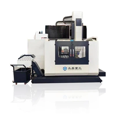
Gantry Machining Center
Machine Tool Features
1. Bed – Worktable
Major components including the bed, worktable, column, crossbeam, saddle, and spindle headstock are manufactured using high-strength cast iron and resin sand casting technology. These components are optimized through 3D CAD software, featuring rationally arranged ribs to enhance rigidity and strength. The machine adopts a fixed-bed gantry framework. The column and crossbeam form an integrated structure, while the worktable moves along the X-axis on the bed. The columns are fixed at both ends of the bed, and the spindle headstock moves vertically along the Z-axis on the crossbeam mounted between the columns.
Bed Guideways: Utilize imported heavy-duty linear roller guides, ensuring excellent accuracy retention, high sensitivity and precision of the worktable, and superior servo drive performance. They offer high load capacity, excellent vibration damping during cutting, which improves overall machine performance, enhances precision and its long-term stability, and extends machine service life.
X-Axis Drive: A servo motor, connected via a planetary reducer (for X-axis models over 3 meters), drives a pre-tensioned ball screw. This mechanism moves the worktable back and forth on the bed, providing X-axis feed motion. The screw pre-tensioning increases the stiffness of the screw assembly.
2. Crossbeam
The crossbeam guideways employ a vertically crossed layout, providing excellent mechanical properties. This design significantly improves cutting accuracy and rigidity, ensures sufficient bending and torsional stiffness of the crossbeam, enabling the machine to handle heavy-duty cutting operations.
Crossbeam Guideways: Utilize imported heavy-duty linear roller guides, known for their excellent accuracy retention. They are suitable for high-power cutting and ensure stable operation.
Y-Axis Drive: A servo motor drives a ball screw, which moves the saddle left and right along the crossbeam, providing Y-axis feed motion.
3. Spindle Headstock
The spindle headstock adopts a ram structure with linear guides. The Z-axis utilizes four guideways, providing excellent vibration absorption and ensuring stable cutting during operation.
Z-Axis Drive: A servo motor drives a ball screw, which moves the spindle headstock up and down on the saddle, providing Z-axis feed motion. The Z-axis servo motor is equipped with an automatic brake that engages during power loss, locking the motor shaft to prevent movement.
Spindle Assembly: Manufactured by a specialized Taiwanese factory, ensuring high precision and performance. Tool clamping is achieved via disc springs on the spindle applying tension through a four-finger claw mechanism onto the pull stud of the tool holder, securing the tool tightly within the spindle taper.The machine features a spindle orientation function.
4. Pneumatic System
Primarily used for tool clamping/unclamping, spindle center through-air, and spindle nose seal air blast.
5. Machine Protection
X-axis bed guideways are protected by stainless steel telescopic covers.
Y-axis crossbeam guideways are protected by bellows-type covers.
The entire machine is fully enclosed to contain chips and coolant splash, ensuring a safe and comfortable working environment for the operator.
6. Lubrication System
Bearings for all three axes are lubricated with grease.
All ball screw assemblies are lubricated automatically with oil.
Guideways for all three axes have automatic lubrication points. Lubricant is distributed to the guideway pairs, with the lubrication cycle automatically controlled by the CNC system.
7. Balancing System
Utilizes a nitrogen-over-oil balancing cylinder to ensure stable movement of the spindle headstock. A hydraulic cylinder is used for tool unclamping, while disc springs provide the clamping force for the automatic tool clamping device.
8. Cooling System
The spindle ram features external tool coolant capability at its nose. Coolant is typically non-corrosive, such as emulsion or light mineral oil.
9. Chip Removal System
Chips generated on the worktable are conveyed by screw conveyors on both sides of the bed to a front-mounted chain-type conveyor.
10. Electrical Cabinet Heat Exchanger
The sealed heat exchanger prevents air exchange between inside and outside the cabinet, effectively blocking moisture, oil mist, and dust. It is compact, lightweight, and requires simple maintenance.
Electrical Cabinet Air Conditioner (Optional): A dedicated cabinet cooler (air conditioner) can be installed based on external environmental conditions. It features electronic temperature control (±1°C), maintaining a constant temperature inside the cabinet, controlling heat, and providing dehumidification to extend the lifespan of electronic components.
11. Tool Magazine Structure (Standard)
The machine is equipped with a reliable Taiwanese-made 24-tool arm-type (disc cam type) tool changer, offering short tool change times.
Chain-Type Tool Magazine (Optional): Offers a 40-tool capacity. It features a double-arm automatic tool changer with a cam-driven mechanism, motor-driven for speed and stability. It includes a large-capacity tool pot storage, driven by a motor and cylindrical cam positioning mechanism for high stability.
12. Spindle Oil Chiller (Optional)
An optional constant-temperature controlled oil chiller prevents thermal growth of the spindle from affecting machining accuracy. It improves machining precision and efficiency, prevents spindle center shift or thermal deformation, extends machine life, stabilizes oil pressure, prevents oil chattering, and operates with low noise.
13. Machine Quality Control
Quality control is implemented through standardized production processes and professional attention to detail. From casting machining to final assembly, every step follows strict, professional standards. Every assembly procedure, every hand scraping operation, and even the tightening of each screw reflects professional manufacturing capability. A product quality management system and a problem responsibility system are in place, ensuring each machine meets leading market standards.
Specifications:
|
Category |
Item |
Specification |
|
Worktable |
Table Size |
2200 mm x 1300 mm |
|
Maximum Table Load |
3 Tons (3,000 kg) |
|
|
Working Range |
X-Axis Travel |
2000 mm |
|
Y-Axis Travel |
1600 mm |
|
|
Z-Axis Travel |
700 mm |
|
|
Gantry Width |
1650 mm |
|
|
Spindle |
Speed Range |
8000 rpm |
|
Maximum Spindle Motor Power |
15 kW |
|
|
Spindle Nose to Table Min./Max. Distance |
65 - 765 mm |
|
|
Spindle Taper |
BT40 / Cat 40 (with 150mm pull stud) |
|
|
Servo System |
3 Axis Motor Torque |
35 / 18 / 18 Nm |
|
Feed System |
Rapid Traverse |
X-Axis: 18 m/min |
|
Y-Axis: 18 m/min |
||
|
Z-Axis: 18 m/min |
||
|
Maximum Cutting Feed Rate |
10000 mm/min |
|
|
Accuracy |
Positioning Accuracy |
X-Axis: ±0.005/300mm |
|
Y-Axis: ±0.005/300mm |
||
|
Z-Axis: ±0.005/300mm |
||
|
Repeatability |
X-Axis: ±0.005mm |
|
|
Y-Axis: ±0.005mm |
||
|
Z-Axis: ±0.005mm |
||
|
Tooling |
Max. Tool Diameter (Adjacent/No Adjacent Tool) |
Ø150 mm / Ø250 mm |
|
Max. Tool Length |
350 mm |
|
|
Max. Tool Weight |
20 kg |
|
|
Tool-to-Tool Change Time |
3.5 sec |
|
|
Utilities |
Air Pressure Requirement |
5 - 7 kgf/cm² (approx. 0.49 - 0.69 MPa) |
|
Overall Dimensions |
Machine Dimensions (L x W x H) |
5850 mm x 3570 mm x 3400 mm |
Main Components List:
|
No. |
Standard Configuration |
Specification / Name |
Origin / Brand |
|
1 |
Control System |
SYNTEC 22MA-4 (All-in-One) |
Taiwan / SYNTEC |
|
2 |
Mechanical Spindle |
Belt-driven, BT40-Ø150 |
Taiwan / Okada |
|
3 |
X-Axis Ball Screw |
R50-12 |
Taiwan / HIWIN |
|
4 |
Y-Axis Ball Screw |
R50-12 |
Taiwan / HIWIN |
|
5 |
Z-Axis Ball Screw |
R50-12 |
Taiwan / HIWIN |
|
6 |
X-Axis Linear Guideway |
45mm Heavy-Duty Roller Guide, 8 Blocks |
Taiwan / HIWIN |
|
7 |
Y-Axis Linear Guideway |
45mm Heavy-Duty Roller Guide, 4 Blocks |
Taiwan / HIWIN |
|
8 |
Z-Axis Linear Guideway |
Turcite-B coated Heavy-Duty Hard Guideway |
Machine Tool Matched |
|
9 |
Three-Axis Screw Bearings |
X: 4072; Y/Z: 3062 |
Japan / NSK or NACHI |
|
10 |
Screw Pre-tension Nut |
YSR |
Taiwan / Yinsh |
|
11 |
Z-Axis Balancing System |
Balancing System |
Wuxi / Huajin |
|
12 |
Centralized Auto Lubrication System |
Volumetric Type |
Hegu |
|
13 |
Pneumatic System |
- |
Taiwan / AirTAC |
|
14 |
Lighting System |
Work Lamp |
Guangdong |
|
15 |
Tool Clamping Cylinder |
Boost Type |
Taiwan / AirTAC |
|
16 |
Electrical Cabinet Heat Exchanger |
Circulation Type |
Taiwan-funded |
|
17 |
Inner Guard (Telescopic Cover) |
Steel Helmet Telescopic Type |
Zhongxin Heavy Industry |
|
18 |
Full Enclosure |
Full Enclosure (Factory Color) |
Zhongxin Heavy Industry |
|
19 |
Chip Removal System |
Two-Screw One-Chain Conveyor |
Zhongxin Heavy Industry |
|
20 |
Oil Chiller* |
- |
Taiwan-funded (Optional) |
|
21 |
Disc-Type Tool Magazine |
24-Tool, Arm Type |
Taiwan / Okada or Shoulun |
|
Note: In case of component shortage, it will be replaced with a substitute of the same specification, same or higher grade, and equivalent brand. * denotes optional item. |
|||
Standard Machining Functions Introduction:
|
No. |
Function (English) |
Description |
|
1 |
Number of Control Paths |
1 |
|
2 |
Maximum Total Controlled Axes (Servo + Spindle) |
6 |
|
Maximum Controlled Servo Axes |
5 |
|
|
Maximum Controlled Spindles |
1 |
|
|
3 |
Simultaneously Controlled Axes |
4 |
|
4 |
Display Unit |
10.4" Color LED |
|
5 |
Servo HRV Control |
High-speed, high-precision servo control |
|
6 |
Program Capacity |
512K (1280m) |
|
7 |
I/O Link i |
1024 / 1024 |
|
8 |
Automatic Data Backup |
Backup of machine tool data |
|
9 |
Memory Card Edit/Run |
DNC / Online Machining |
|
10 |
Program Folder Management |
Functions for using macro programs and machining programs |
|
11 |
FSSB High-Speed Rigid Tapping |
Reduces rigid tapping time and error |
|
12 |
Intelligent Backlash Compensation |
Backlash compensation |
|
13 |
PMC Axis Control |
Used when tool magazine is a servo-driven type |
|
14 |
Data Transmission via Embedded Ethernet |
Data transmission function via Ethernet |
|
15 |
USB to CF Card Program Transfer |
Data transmission function |
|
16 |
Servo Guide Mate |
Servo optimization |
|
17 |
Spindle Intelligent Load Meter |
Monitors spindle current and other statuses |
|
18 |
AI Contour Control |
Optimal speed and acceleration control with look-ahead |
|
19 |
Smooth Tolerance Control |
Determines appropriate machining speed via commanded tolerance |
|
20 |
Intelligent Overlap |
Reduces part machining cycle time |
|
21 |
Spindle HRV Control |
High-speed, high-precision servo control |
|
22 |
Inch/Metric Conversion |
Conversion of machine tool units |
|
23 |
HRV2 Control |
High-speed, high-precision servo control |
|
24 |
HRV3 Control |
High-speed, high-precision servo control |
|
25 |
SYNTEC 22MA-4 All-in-One |
Servo tuning for high-speed, high-precision machining in a short time |
|
26 |
Flexible Feed Gear |
Arbitrary DMR |
|
27 |
Least Command Increment (0.0001mm, 0.0001deg, 0.00001 inch) |
Minimum system unit |
|
28 |
Mirror Image |
For each axis |
|
29 |
Rigid Tapping Retract |
Rigid tapping retract |
|
30 |
Buffer Register |
System data buffer |
|
31 |
Positioning (Spindle Orientation) |
Spindle positioning function for tapping, tool change |
|
32 |
Linear Interpolation |
Linear machining function |
|
33 |
Circular Interpolation |
Circular machining function |
|
34 |
Helical Interpolation |
Helical machining function |
|
35 |
Thread Cutting, Synchronous Feed |
Thread cutting, synchronous feed |
|
36 |
Rotary Axis Rollover |
Rotary axis rollover |
|
37 |
Chamfering/Corner R at Any Angle |
Chamfering/Corner R at any angle |
|
38 |
Canned Cycles for Drilling |
Canned cycles for drilling |
|
39 |
Dogless Reference Point Setting |
Dogless reference point setting |
|
40 |
Automatic Corner Override |
Automatic control of feed override at corners |
|
41 |
Scaling |
Scaling |
|
42 |
Plane Selection |
G17, G18, G19 |
|
43 |
Programmable Mirror Image |
Programmable mirror image for each axis |
|
44 |
Single Block |
Program execution in single blocks |
|
45 |
Program Restart |
Restart after temporary program interruption |
|
46 |
Tool Diameter / Nose Radius Compensation |
Tool parameter compensation |
|
47 |
Tool Life Management |
Tool life management |
|
48 |
Extended Tool Life Management |
Extended tool life management |
|
49 |
Backlash Compensation |
Machine axis backlash compensation function |
|
50 |
Position Tracking |
Position tracking |
|
51 |
Abnormal Load Detection |
Abnormal load detection for each axis |
|
52 |
Position Switch |
Program protection function |
|
53 |
Background Editing |
Program editing possible in edit mode |
|
54 |
Multi-language Display Function |
10 system operation interface languages |
|
55 |
Self-diagnostic Function |
Monitors machine tool status |
|
56 |
Help Function |
View system alarms |
|
57 |
Nano Interpolation |
Nano interpolation |
|
58 |
Work Coordinate System |
G52 ~ G59 |
|
59 |
Absolute/Incremental Command |
Can be mixed within the same block |
|
60 |
Fault Diagnosis |
Checks current machine tool fault conditions |
|
61 |
Screen Clear |
Manual or automatic screen clearing |
|
62 |
Power Consumption Monitoring |
Monitors machine tool power consumption |
Machine Tool Working Environment Conditions:
Three-Phase AC Power Supply: 380V ±10% ~ 15%; 50Hz ±1Hz. Main power cable: 8mm² or larger. Grounding wire: 8mm² or larger.
Ambient Temperature: 8 ~ 40 °C.
Relative Humidity: ≤ 80%.
Keep away from strong light sources, vibration sources, and heat sources. Keep away from high-frequency generators, discharge equipment, welding machines, etc., to avoid electrical interference that may cause faults in the machine's NC system.
Recommended Oils and Greases Chart:
|
Lubrication Part |
Quantity |
Recommended Lubricant |
|
Notes |
|
|
Ambient Temp. 10~40°C |
Ambient Temp. 5~10°C |
||||
|
Ball Screws |
Oil Lubrication |
2-4 Liters |
Way Oil #68 |
Way Oil #32 |
1. Check and refill daily before operation or when an alarm appears. |
|
Grease Lubrication |
0.7-0.8 Liters |
Lithium Grease #000 |
2. Change oil grade for low temperatures. |
||
|
3. For grease cartridges, the brand must match the lubricator manufacturer. |
|||||
|
Spindle & Screw Cooling Unit |
Water Chiller |
15-35 Liters |
BASF G48 Antifreeze (No other medium allowed) |
- |
1. Check and refill antifreeze/oil daily before operation or when an alarm appears. |
|
Oil Chiller |
20-40 Liters |
Great Wall No. 10 Spindle Oil |
Great Wall No. 5 Spindle Oil |
2. Change oil grade for low temperatures. |
|
|
Hydraulic Station |
25 Liters |
Hydraulic Oil HM #32 |
Hydraulic Oil HM #20 |
1. Check daily before operation; change oil annually. |
|
|
Booster Cylinder |
0.1-0.2 Liters |
Hydraulic Oil #32 |
Hydraulic Oil #20 |
1. Check daily before operation; refill when oil cup is only 1/3 full. |
|
|
Cutting Fluid |
100-350 Liters |
Select appropriate cutting fluid based on workpiece material & machining conditions (quantity based on actual tank capacity). |
- |
Check for ice in the tank before startup when ambient temp. is below 5°C. |
|
|
4th Axis |
0.8~1 Liters |
Gear Oil #150 |
Gear Oil #100 |
1. Check daily before operation; change oil every 6 months. |
|
|
Tool Changer Arm System |
7 Liters |
Gear Oil #100 |
15W-40 Antifreeze Diesel Engine Oil |
1. Check daily before operation; change oil every 2400 operating hours or 6 months. |
|
Hot Tags: gantry machining center, China gantry machining center manufacturers, suppliers, factory, cnc horizontal machining center coolant system, cnc horizontal machining center table, cnc horizontal machining center for packaging, cnc horizontal machining center for trade shows, cnc horizontal machining center for green manufacturing, cnc horizontal machining center for refunds guides
Previous
No InformationYou Might Also Like


Send Inquiry