



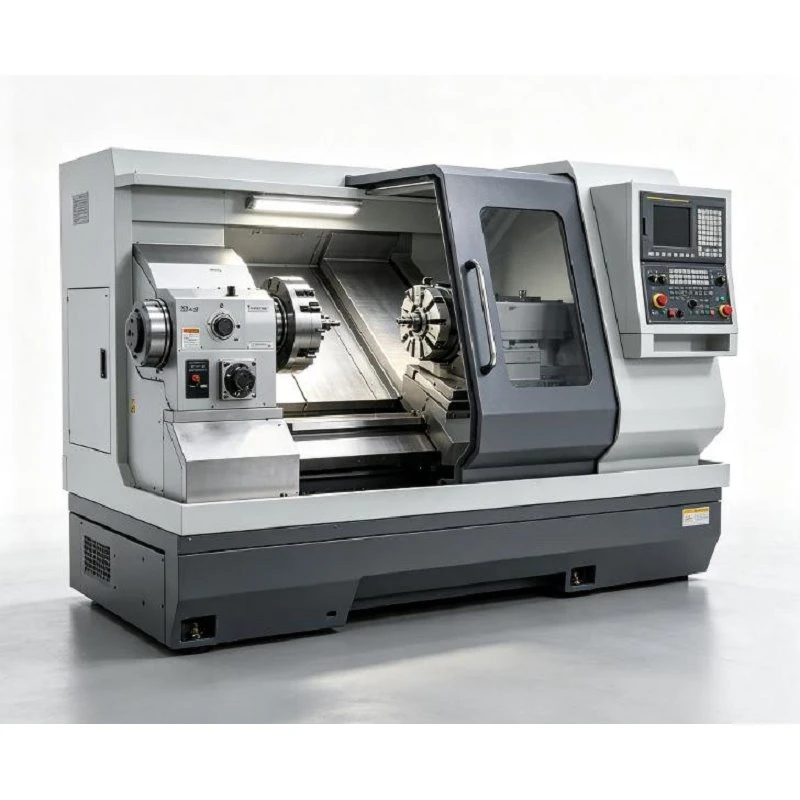
Multi Axis Precision CNC Lathe
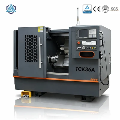
The Multi-Axis Precision CNC Lathe is engineered for complex turned components requiring secondary milling, drilling, tapping, or complete back-working in a single setup. By integrating Y-axis, C-axis, live tooling, and sub-spindle capabilities with primary X/Z turning axes, workpieces remain precisely clamped, eliminating multiple transfers between separate machines.
Technical Specifications
|
Parameter |
Specification |
|
Machine Type |
Multi Axis Precision CNC Lathe |
|
Max. Swing Over Bed |
560 mm |
|
Max. Swing Over Cross Slide |
300 mm |
|
Max. Processing Length |
500 / 800 / 1250 mm |
|
Spindle Unit |
200 / 230 mm |
|
Spindle Nose |
A2-6 / A2-8 |
|
Spindle Motor |
11 / 15 kW |
|
Max. Spindle Speed |
3000 rpm |
|
Spindle Bore |
66 / 86 mm |
|
Bar Capacity |
55 / 75 mm |
|
X-Axis Travel |
240 mm |
|
Z-Axis Travel |
540 / 860 / 1300 mm |
|
X-Axis Motor Torque |
10 / 15 N·m |
|
Z-Axis Motor Torque |
10 / 15 N·m |
|
X/Z Repeat Positioning Accuracy |
±0.003 mm |
|
Turret |
12-Station Power Turret with Y Axis |
|
Y-Axis Travel |
±50 mm |
|
Turret Center Height |
100 mm |
|
Hydraulic Quill Diameter |
70 mm |
|
Hydraulic Quill Traverse |
80 mm |
|
Hydraulic Quill Taper |
MT5 |
|
Hydraulic Tailstock Travel |
450 mm |
|
Machine Dimensions |
2700 / 3300 / 3750 × 2000 × 2000 mm |
|
Machine Weight |
3600 / 4500 / 5200 kg |
Industry Applications
Automotive: Transmission shafts, bushings, couplings, custom valves, and stepped pins.
Hydraulics & Pneumatics: Valve spools, hydraulic adapters, manifolds, sleeves, and rod ends.
Industrial Machinery: Pump shafts, drive connectors, sleeves, and motor housings.
Precision Electronics & Hardware: Electrical connectors, precision bushings, and sensor housings.
Machine Structure
High-Rigidity Machine Bed: Built on a 30-degree or 45-degree one-piece heavy-duty cast iron bed (Meehanite cast) to absorb vibration, minimize thermal deformation, and allow aggressive metal removal rates.
Precision Spindle System: High-torque main and sub-spindles with thermal displacement compensation, engineered for stability across steel, titanium, and non-ferrous alloys.
Linear / Box Guideways: Hardened and ground guideways offer rigidity for heavy-duty cutting and rapid response for precision finishing.
Driven Tool Turret: BMT or VDI interface driven tool stations deliver direct power for high-speed milling and drilling without torque loss.
Coolant & Lubrication: Automated centralized lubrication paired with optional high-pressure coolant (20 to 70 bar) ensures efficient chip evacuation in deep-hole drilling and extended insert life.
Process Capabilities
Turning: External turning, facing, internal boring, precision grooving, metric/UN threads, variable pitch threading, and contouring.
Milling: Face milling, side milling, off-center slots, keyways, polygonal machining, and helical interpolation.
Drilling & Tapping: Centerline drilling, radial cross-holes, off-center drilling, rigid tapping, and peck drilling cycles.
Second-Side Transfer: Automatic synchronized main-to-sub-spindle transfer for complete rear-side operations without manual intervention.
Material Compatibility
Carbon & Alloy Steels: Optimized spindle torque for rigid roughing on AISI 1045, 4140, 4340.
Stainless Steel: High-rigidity guideways prevent chatter when machining 304, 316L, 17-4PH, and Duplex grades.
Non-Ferrous Metals: High spindle speeds up to 5,000 RPM for clean surface finishes on Aluminum (6061-T6, 7075), Brass, and Copper.
Engineering Plastics: Clean chip disposal and stable tool motion for PEEK, POM (Acetal), and Nylon components.
Workholding & Automation Options
Workholding Solutions: Hydraulic 3-jaw chucks, precision collet chucks, custom soft/hard jaws, and tailstock centers.
Bar Feeders: Matched to 55 mm or 75 mm bar capacities for continuous raw stock feeding.
Parts Catchers & Conveyors: Supports continuous lights-out production and high-volume chip removal.
Quality Assurance
Every unit undergoes rigorous factory pre-shipment inspection:
Mechanical & Alignment: Bed leveling, guideway straightness, ball screw backlash, and spindle runout testing.
Axis & Servo Testing: Travel limits, smooth motion profiles, and positioning repeatability checks on X, Y, and Z axes.
Turret & Live Tooling: Indexing accuracy, station locking force, and live tool spindle runout under load.
Hydraulic & Thermal Run-In: Extended operational run-in to verify seal integrity, pump pressure, and thermal stability.
FAQ
Hot Tags: multi axis precision cnc lathe, China multi axis precision cnc lathe manufacturers, suppliers, factory
You Might Also Like

Send Inquiry